- How to log in to the User Interface
- Open the FSM
- Open the log file
- Load the PIT configuration from the database
- Exclude one half-stave or chip from the Link Configuration
- Set and read the output algorithms parameters
- Check for noisy chips
- Check the phase alignment (of the data stream wrt PIT timer)
- [FOR EXPERTS] How to restart the pitFed driver
- [FOR EXPERTS] How to link the configuration version inside ACT
- [FOR EXPERTS] RORC driver/kernel incompatibility
How to log in to the User Interface
-
from the Start button go to PIT ON
-
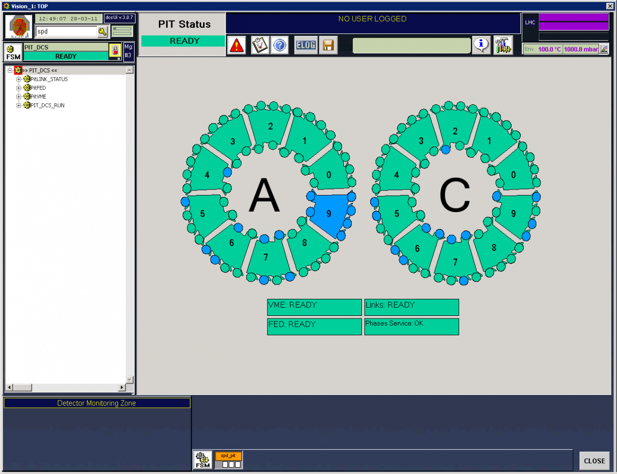
the PIT user interface (UI) opens automatically, log in with the "spd" username. The detector is schematically reproduced and the color logic is the following:
If all the half staves required from the trigger logic are in ready state in the SPD, then the PIT general status is ready.
Open the FSM
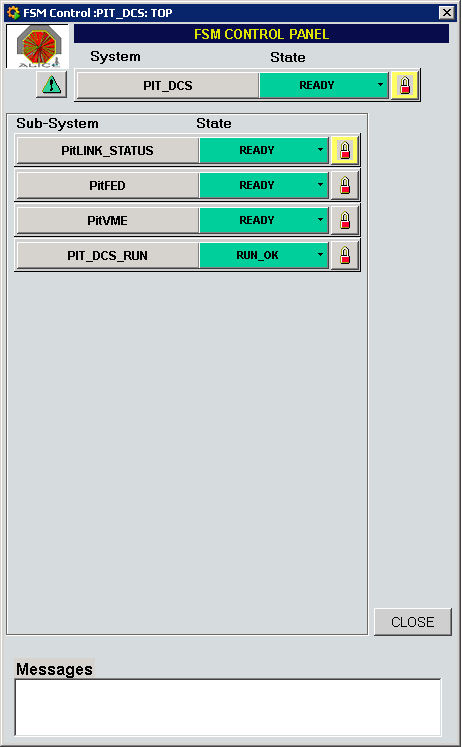
- make sure that the panel displayed is the SPD_DCS, if not, go there from the menu on the left
- press the FSM button in the upper left corner of the UI
- take the control pressing the padlock and selecting "Take"
Open the log file
- open an XTerm and log to the machine: ssh apixel@alispdpit1
- go to the folder pitFed and execute tail -f pit.log for live monitoring of the log file
Load the PIT configuration from the database
- from the menu on the left open the PitFED, right click on "pitFedStatus" and open the panel
- go to the tab "Configuration", in the center of the panel you can see 3 buttons corresponding to the 3 different information stored in the database. The most used one is the "Link DB Configuration", to retrieve or save the PIT masks; the principle of operation of the others are the same
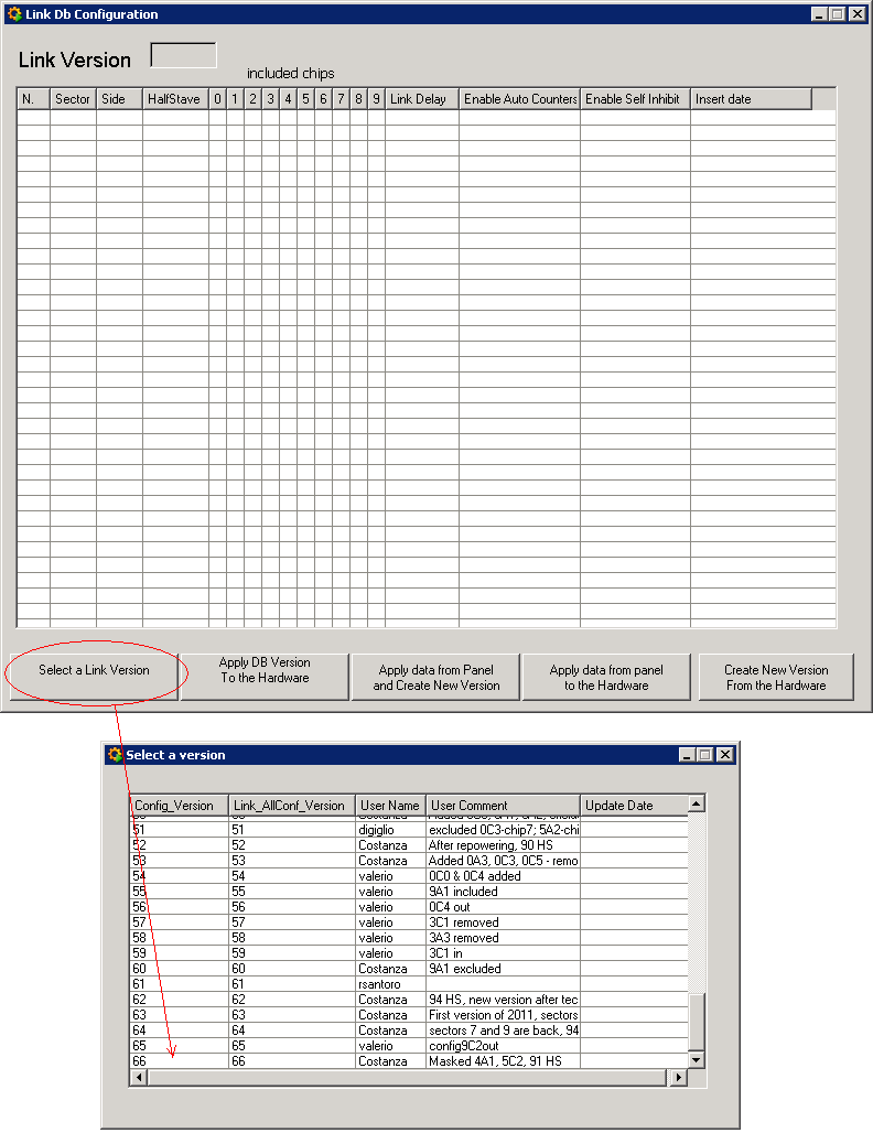
- press on the button "Link DB Configuration", a new panel will open. Press on the button "Select a Link Version" and choose one database version to load. Then click on the button "Apply DB Version To The Hardware".
Exclude one half-stave or chip from the Link Configuration
- from the menu on the left open the PitFED, right click on "pitFedStatus", open the panel and go to the tab "Configuration"
- press on the button "Link DB Configuration", a new panel will open. Press on the button "Select a Link Version" and choose one database version to load
- apply the desired changes: the chips included in the trigger logic are with a tick mark, the masked chips correspond to empty boxes
- click on the button "Apply data from panel to the hardware". Eventually, when the changes are fully checked, create a new DB version by clicking on the button "Create new version from the hardware"
Set and read the output algorithms parameters
Refer to the Pixel Trigger page for the list of the algorithm parameters
- from the menu on the left open the PitFED, right click on "pitFedStatus", open the panel and go to the tab "Configuration". On the left side of the panel there are two buttons to set a parameter of an algorithm (Set Algorithm Parameter) and to read it back (Get Algorithm Parameter)
- to set a parameter, write the algorithm selection number, write the parameter number and the desired value. Press on the button "Set Algorithm Parameter"
- to read a parameter, write only the algorithm selection number and the parameter number. Press on the button "Get Algorithm Parameter"
Check for noisy chips
- from the "PitFedStatus" panel go to the tab "Configuration"
- start and stop all the counters with the buttons "start all counters" and "stop all counters". Wait at least 10 seconds between the two commands
- set an appropriate threshold (i.e. 50) and click on the button "find noisy chips". Check the log underneath for the noisy chips
- eventually mask the single chips following the instructions on how to exclude one chip from the Link Configuration here
Check the phase alignment (of the data stream wrt the PIT timer)
- check the indicator "Check Phases" on the main PIT panel: it has to be green when the SPD is included in a run
-
if the indicator is red the phases are not aligned
- go to the PIT_DCS main panel and click on "Restart Phases Service"
- if the "Check Phases" is still red, call the expert
- write an entry in the Logbook.
NOTE for the expert: to determine which channel(s) is(are) not aligned, one can generate a report of phases by the pitFed issuing the command auto_check_phases in the advanced panel of the PitFED DCS GUI (or pressing the button "Auto Check Phases" on the Configuration tab. The report is produced in the log file, see instructions above to monitor the log file on alispdwn005 to read the phases report.
[FOR EXPERTS] How to restart the pitFed driver
NOTE: you see if the driver is stopped if you launch some commands and the indicator in the top right corner of the pixel trigger user interface remains grey
- open an XTerm and log to the machine: ssh apixel@alispdpit1
- launch "./run_pitFed start"
- then from the User Interface load the last parameters and links configuration from the database (see Load the PIT configuration from the database)
[FOR EXPERTS] How to link the configuration version inside ACT
- click on FERO CC button (top right, with the tools icon)
- from the Detector menu choose PIT
-
specify that a DB version can be considered as good (and linkable)
- click on "Allowable versions" and select the version that you want to link
- from the Subsystem menu choose Firmware, Firmware parameters or Link configuration depending on the version you want to link. Usually it is Link configuration
- insert a Description and click on "Set version as allowable"
-
now link this version to the correct run type
- click on "current versions"
- select the run type (usually PHYSICS) and click on Modify
- from the Subsystem menu choose Firmware, Firmware parameters or Link configuration. BE CAREFUL: in case the Link is modified remember to apply the changes for both the parameter values Defaule and CINT1_900
- select the version from the "Allowable versions" table and click on "Set as current version"
- exit from the panel and check with the refresh button that everything is correct
[FOR EXPERTS] RORC drivers / kernel incompatibility
-
The physmem and rorc drivers, installed in the machines via RPM, only work with a specific version of the linux kernel. Each time there is a new kernel version, we need to prepare new RPMs. For the PIT machines, the drivers version is 2.6.32-431.17, the same as the kernel version at the time the machine was installed:
[root@alidcscom351 ~]# rpm -qa | grep rorc-kernel-module
mrorc-kernel-module-3.1.2-2.6.32_431.17.1.el6.x86_64.x86_64
rorc-kernel-module-7.1.4-2.6.32_431.17.1.el6.x86_64.x86_64
[root@alidcscom351 ~]# rpm -qa | grep physmem-kernel-module
physmem-kernel-module-6.7-2.6.32_431.17.1.el6.x86_64.x86_64
In the meantime, there was a kernel upgrade performed by YUM to version 2.6.32-431.20 (in fact two kernels were installed, but the latest - 2.6.32-431.23 - was never loaded because the machine didn't reboot since then). This breaks the compatibility with the drivers and therefore the RORCs are not detected any more.
Solution:
============
1) Disable SLC6 updates repository
- edit /etc/yum.repos.d/slc6-updates.repo and, for the [slc6-updates] block, set the enabled parameter to zero.
2) Change the default kernel to load at boot time (older kernel versions remain installed on the machine, so we can tell the linux boot loader, GRUB, to load the old correct kernel)
- edit /etc/grub.conf and change the "default" parameter to 2 (this parameter specifies the index, starting from zero, of the kernel to load. In the PT machines there are 3 installed kernels - 23, 20 and 17 - so we want number 2: 17).
3) reboot the machine