Error Handler description
All the errors coming from the different sub-systems are collected and elaborated from each Router. Some error classes are defined, and they are elaborated by a combinatory logic called Priority Encoder (PE), which keeps trace of the real errors and limits as much as possible the cascade errors derived from them.
The table below lists the different number of error signals that there are in each Router.
| Sub-system | Number of error signals |
| Trigger | 50 |
| Router | 11 |
| Link Rx | 54 |
| Half-stave | 30 |
| Optical connections | 15 |
| TOTAL | 160 |
For the entire SPD this translates into a total of 3200 error signals, moreover usually one single error can generate a cascade of other errors in the detector.
Therefore, a strategy to manage all the error signals is necessary in order to give a clear error message to the shifters.
This translates into two different levels of actions:
Therefore, a strategy to manage all the error signals is necessary in order to give a clear error message to the shifters.
This translates into two different levels of actions:
- locally (router level): creation a new module in the FPGA firmware;
- globally (software level): collection of all the local errors and indication of the actions to follow in order to put the SPD in a proper operating status.
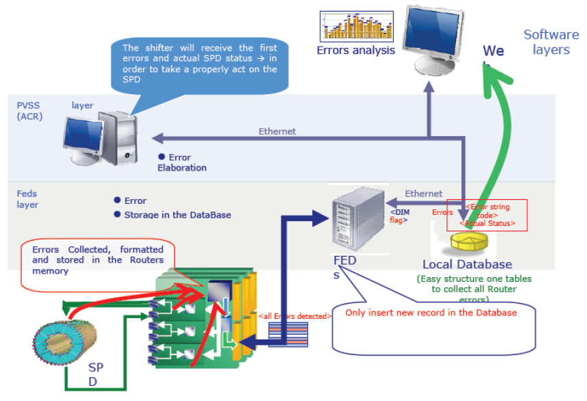
The total amount of errors that each router is able to detect is very large, so both hardware and software strategies are needed in order to properly analyze the errors of the whole SPD.
Two tiers are needed for the software layer:
Two tiers are needed for the software layer:
- low level: Front-End Device (FED) and Oracle DBMS;
- high level: PVSS graphic user interface.
The Oracle database is used to store all the errors coming from the routers, so that a common repository is present for additional statistical studies on the electronics and for the detector debug.
The hardware level is implemented on an Altera Stratix FPGA1
The following actions are performed: placed on each Router. This FPGA is principally used as the Router main processor.
The following actions are performed: placed on each Router. This FPGA is principally used as the Router main processor.
- errors detection at 40 MHz, filtered by a Priority Encoder (PE);
- errors formatting;
- management of the errors data (by single memory with FSM);
-
read back from the FED
The hardware architecture contains several logic blocks that are shown below