Calibration of the SPD spare sector in DSF
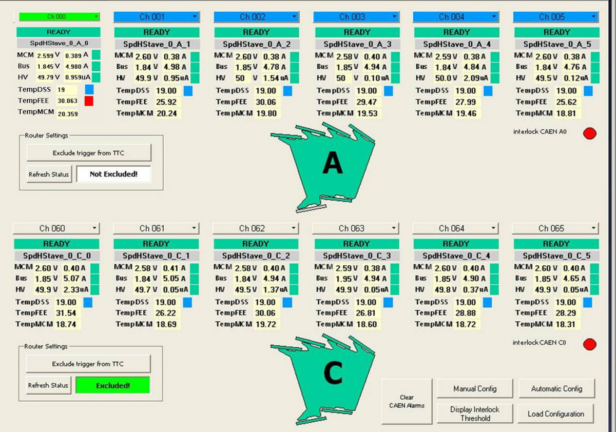
Summary: succesful powering on. Secuirty system reliable, cooling stable, PVSS working and stable, HS configuration optimized.
To do:
-
Fast-OR:
- Optical Splitters to be received, to be installed (tbd a patch-panel) in the rack.
- PIT software (fed + PVSS) to be set up
- Fo chips configuration to be optimized
- 90Sr source test and cosmic data-taking with FO trigger
Powering on again 12/12 HS ON..

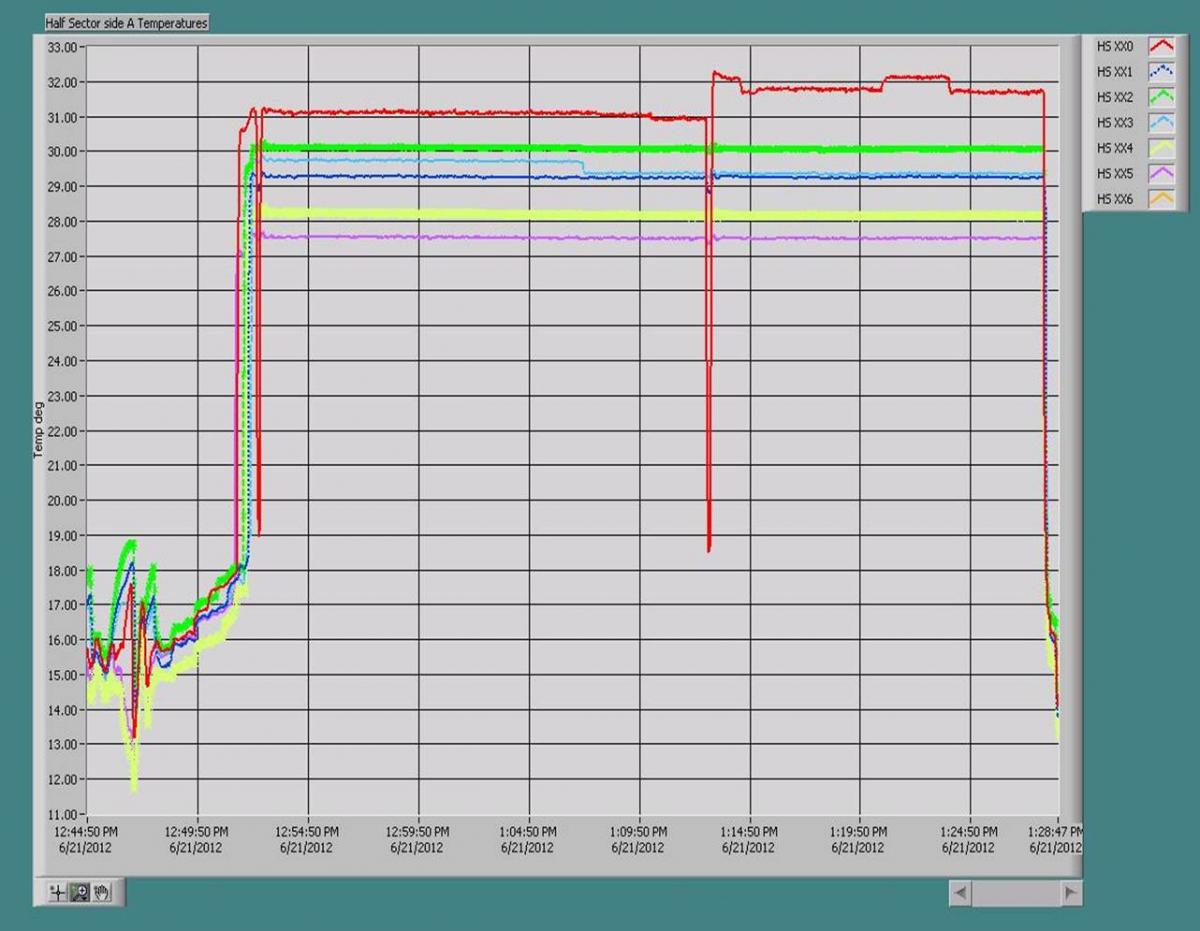
Low and stable temperatures with configurations optimized.

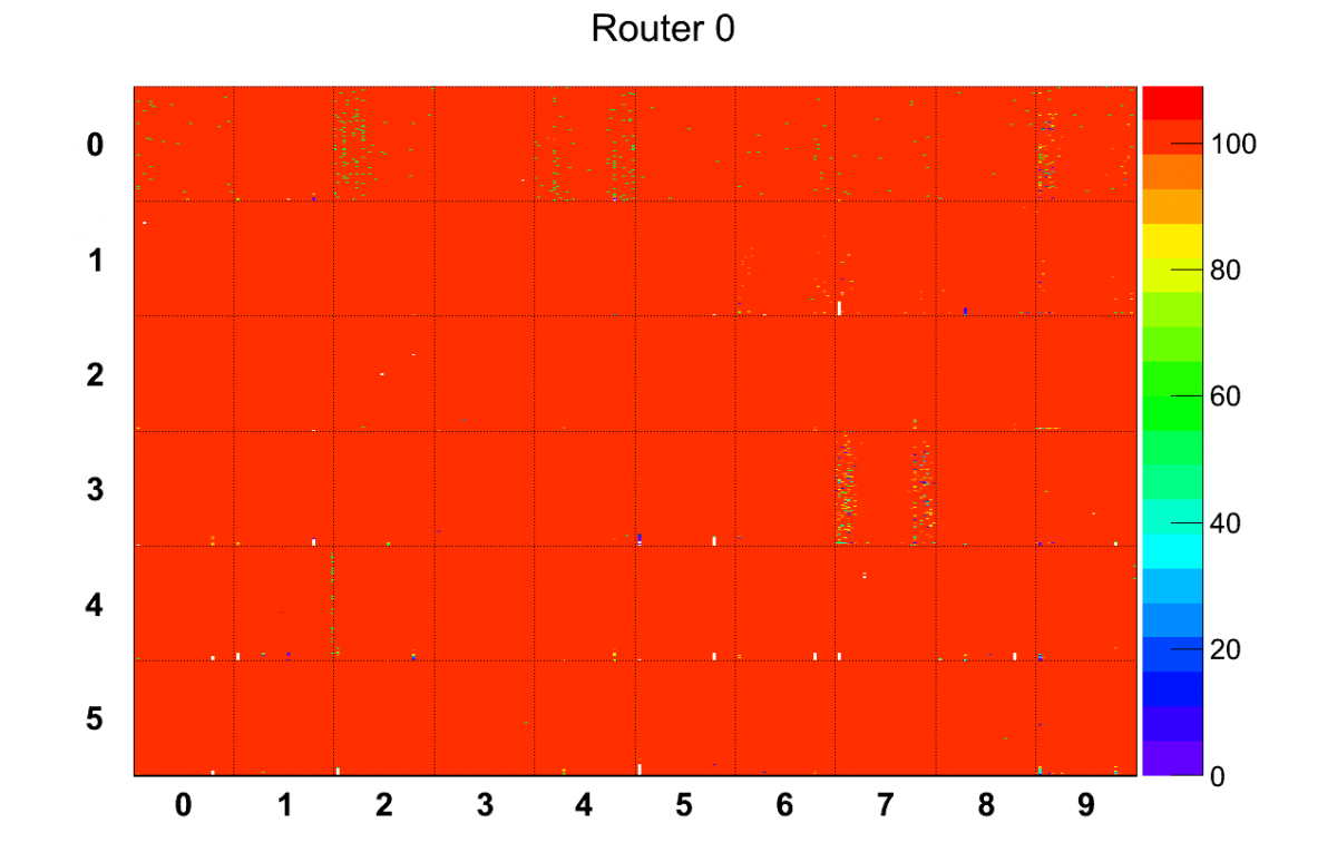
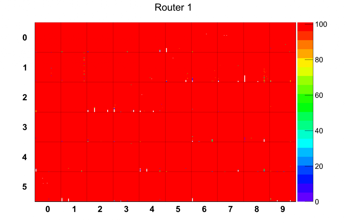
FEE optimization, Uniformity Matrix Scan performed


Remarks:
- 4 noisy pixel masked.
- 0A0 Chip 0-2-4-6-7-9 show inefficiencies, not possible to improve anymore. To check with 90Sr source.
- 0A3 Chip 7 shows inefficiencies, not possible to improve anymore. To check with 90Sr source.
- 1A2 Chip 1 (i.e. 0C2 Chip1) shows column test with double countings. To check with 90Sr source.

- Cooling specs:
working pressure 2.94 bar
working flow 2.01 g/s
- Safety specs:
Redundant Interlock system installed, logical OR of
- Router Temperature
- PT1000 chain Temperature readout via HP DAQ
- PLC Cooling loop-OFF
- Software/CAEN
- PVSS for CAEN follows the right convention of Side A and C
- The routers are both in Side A. The CAEN Side A is Eq0. The CAEN Side C is Eq1.
- New Daq PC (SLC5) with 3 RORCS installed.
- SPDMood working properly, SPD DA installed + RefDisplay (instructions soon)
