Index
Printable version here
- Colour convention for the device
- FSM padlock states and colours
- How to log in to the user interface
- Control the FSM
- Switch On the detector
- Switch On a half stave
- Switch Off the detector or a half stave
- Release the FSM Control
- What to do when a half stave goes “HOT”
- Clear CAEN alarms
- Release a tripped channel or one in a state of error
- Interpret alert messages: how to handle DSS alarms
- [FOR EXPERTS] How to restart the FSM
- [FOR EXPERTS] How to stop/restart WinCC projects
- [FOR EXPERTS] How to link the last configuration version inside ACT
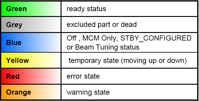
Colour Convention For The Devices
FSM padlock states and colours
- Unlocked - grey: excluded - no one has control of the FSM. No commands can be issued.
- Locked - green: the SPD user has exclusive control over the FSM and only him/her can issue commands.
- Locked - red: the partition is operated in exclusive mode by another PC. Commands may not be issued from the SPD user’s PC.
- Locked - yellow: the partition is shared but not operated by the SPD user’s PC. All the same, SPD users and others may issue commands.
- Locked - blue: the partition is shared and operated by the SPD user’s PC. SPD users and others may issue commands.
How to log in to the user interface
To start an Xterm window, click the XTerm icon on your desktop or from the drop-down menus.
Now it is possible to connect to the operator node giving the following command after the prompt:
- rdesktop –a16 –g3800x1100 alispdon001 & and click return. The input “3800x1100” defines the screen size (double screen in this case). Users can choose to use 1900x1100 which corresponds to a single screen. Login using your NICE username and password.
- The SPD user interface (UI) opens automatically and to login the relative "SPD” user and password are requested.
- In case the User Interface does not automatically open or the panel is closed by mistake, users should go to Windows start menu and click “spdUserInterface.exe”
Control the FSM
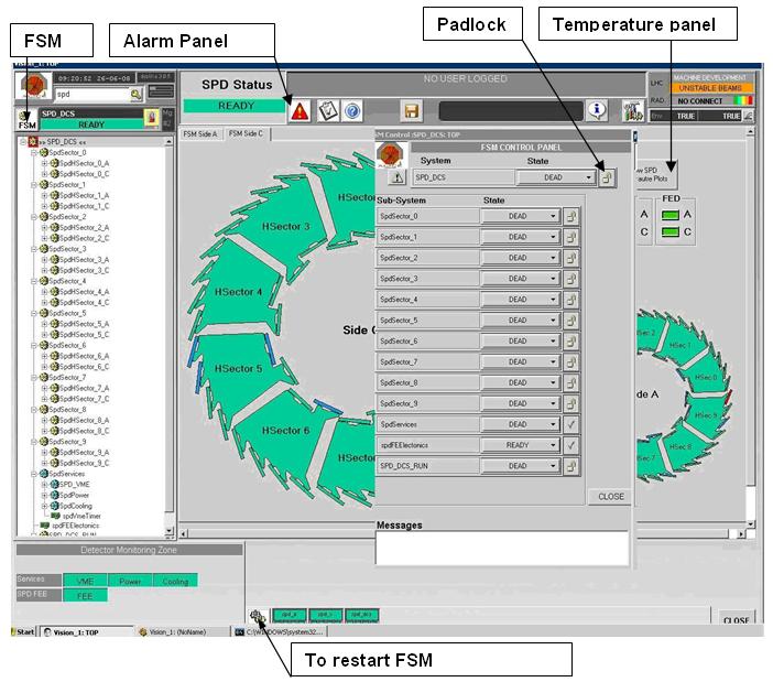
Figure 1: Main Detector Control System (DCS) panel and FSM panel
- Press the FSM button on UI top left to open the FSM control top node.
- Take the hand pressing the key button and selecting TAKE.
Switch On the detector
The actual detector switching on procedure requires the half staves to be switched on one at a time.
- Check at the FSM top node (SPD_DCS) is selected before clicking the FSM button
- Gain control of the FSM (if not already gained) by clicking on the padlock on the top node and select “Take”
- Switch On the VME communication of the detector. In the FSM Panel double click on the “SpdServices”, then click the SpdVME button and select “ON”
- Switch On the power supply of the detector: In the FSM Panel double click on the “SpdServices” and then double click on the “SpdPower” button. Click on “SY1527”, the 2 channel000 and the 2 channel 001 buttons and select “ON” each time
- Open the cooling lines
-
Clear the interlocks in the main DSS alarms panel (it is always open in the DCS position, in case of doubts ask the DCS shifter).
In the panel, the detector and the device names are in the 2nd column, the 3rd column shows the logic name which is useful to understand where in the detector the problem has occurre, the 4th column provides a short description of the kind of error that has occurred. To clear an alarm, click on its name - If all loops are open and all the interlocks are cleared, on the main SPD_DCS panel the "Caen Interlock" indicator has to be green
- Clear the CAEN alarms
- Go to SPDFEElectronics and click on "AutoConfig Routers". If the routers have also switched off (i.e. power cut) open Manual Config -> Router settings -> Panels for experts -> Initialize routers and initialize all routers; also click on Manual Config -> Router settings -> RESET TTCrx to reset the TTCrx chip.
-
Make sure that the good configuration is loaded. Go to SPDFEElectronics and click on "Load config file" (Fig. 4, n.2).
Click on "Load detector config", select the last version and click "Select".
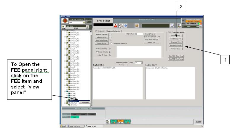
Figure 4: FEE main panel

Figure 5: Load Config file panel
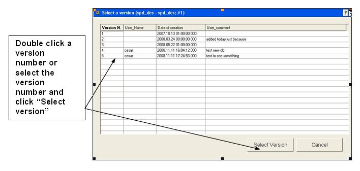
Figure 6: Load version panel
-
In the FSM panel double click on the sector you want to switch on. The following procedure has to be followed for all the half staves that the user wants to get READY :
- in the FSM panel click the half stave to be switched on and select GO_MCM_ONLY from the pull-down menu (this command can be given for all half staves of a same sector all at once from the sector top node);
- open the "Automatic config" panel and go to the half-stave you want to switch on;
- from the MCM_ONLY state select the command GO_STBY_CONFIGURED from the pull-down menu in the FSM panel; when the state STBY_CONFIGURED is active (module is blue) click on "Config HS" in the Automatic config panel;
- when all the half staves of a sector are in the STBY_CONFIGURED state it is possible to give the command GO_READY to all of them at once from the sector top node. The user can chose to give the command to all half staves one by one or to all of them all at once.
- If anything goes wrong during the power-on or during the configuration, call the expert
Switch On a half stave
- Check that the FSM top node (SPD_DCS) is selected before clicking the FSM button.
- Gain control of the FSM (if not already gained) by clicking on the padlock on the top node and select “Take”; following the procedure explained in the next figure the user can reach the sector hosting the half stave that got Hot (red).
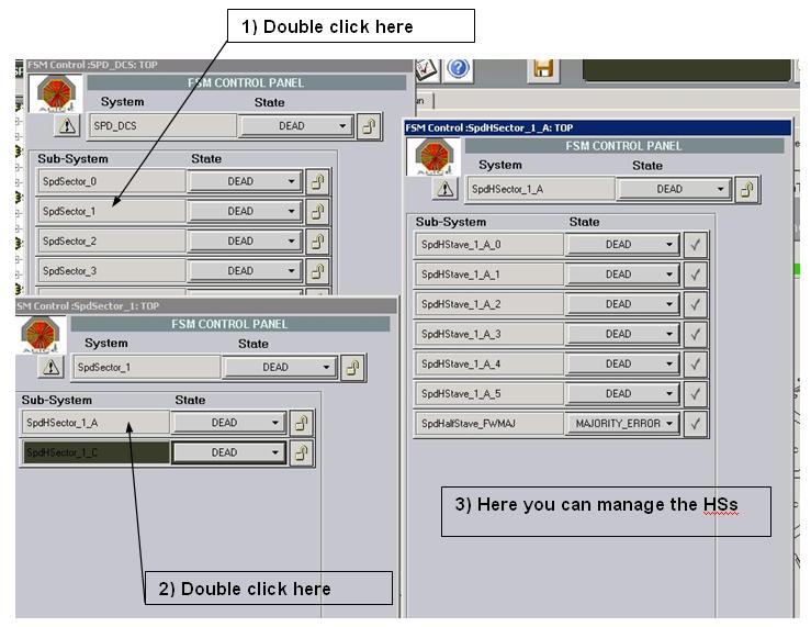
Figure 7: Follow the sequence numbers to open the child FSM panels
-
A pull-down menu opens by clicking on the concerned Half stave; select “Release” from the pull-down menu. Like this the half stave should switch to McmOnly.
If the error state persists it means that an alarm may still be active. Check with the DCS shifter.
- From the McmOnly state select the command Go_STBY_CONFIGURED from the pull-down menu in the FSM panel; when the state STBY_CONFIGURED is active click on Configure Half stave (Fig.8, n.2).
- From the STBY_CONFIGURED state select the Go Ready command from the pull-down menu in the FSM panel.
Switch Off the detector or a half stave
- Check that the FSM top node (SPD_DCS) is selected before clicking the FSM button.
- Gain control of the FSM (if not already gained) by clicking on the padlock on the top node and select “Take”.
- Double click on the half stave to be switched OFF (repeat for all the half staves that have to be switched off).
- From the Ready state (or STBY_CONFIGURED state) select Go Off from the pull-down menu in the FSM panel.
- If it is necessary to switch OFF the cooling plant or part of it, the user can follow the procedure explained in the section: Switch Off The Cooling Plant Or Close A Loop.
Release the FSM Control
Procedure to follow when ALL the half-staves of the router are excluded from the FSM.
- go to Manual config -> Router settings
- tick "Exclude trigger from TTC" and "High multiplicity in CDH" and click "write"
- go to Manual config -> FanInFanOut
- untick to remove the router you want to exclude, click on write and then read for confirmation
- go to DCA - Alice DAQ panel and open "Select equipment"
- exclude the router
- click "Commit" and then "Quit"
What to do when a half stave goes “HOT”
- from the SPD main panel, click on the HS in error state; a new panel opens, with the control of this HS (no need to ask it to the DCS)
- release the error, the HS will automatically go to MCM_ONLY state
- either try to switch it on again (remember to configure + mask), or exclude it from the FSM
- if all the HS of one router are excluded from the FSM, follow the procedure to exclude the router from the data taking
- if a software interlock happened, all the HS of the router will be switched OFF and a CAEN interlock will appear; in this case clear the alarms from the DSS station and switch on the HSs again
Clear CAEN alarms
- Open the spdPower branch in the FSM tree. Right-click on the link SY1527 to open the main power control panel.
- If it is necessary to clear alarms, click the Clear Alarms push-button (fig. 9, n.1).
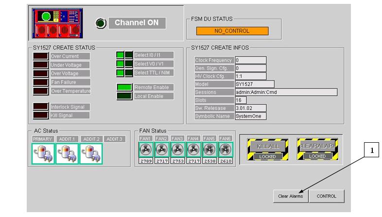
Fig. 9: Caen control panel
Release a tripped channel or one in a state of error
- Navigate through the FSM to the half-stave in ERROR, the red one. Its name/number and the time the error or trip has taken place must be written in the logbook.
- To release the error go to the panel of the sector with the HS in ERROR, and click on "Clear CAEN alarms". At this point, from the FSM menu select RELEASE and check that the half-stave goes to a safe blue state.
- If the detector is in READY, bring the HS to READY again.
- BEAM ON: in case the beam is on, the error has not recovered, and it is necessary to restart the Run, exclude the half-stave from the FSM tree, check that the top SPD_DCS node is again READY or BEAM_TUNING. The run can now be restarted.
If there is a PERSISTENT ERROR ON THE HV go to the HV modules in CR4 (on the back side of the mainframe) and disconnect the 50Ohm termination on the bottom of the faulty module. NOTE: there are 10 modules, one per sector, with sector 0 on the left and sector 9 on the right.
----------------------------------------------------------------
Once the half stave that run into an error or tripped state has been detected, it is possible to open the FSM tree branches that concern it. As shown in the figure n.6, the branch spdHSPW can be found inside the FSM hierarchy of a half stave; 6 more branches open by clicking on it and one of them is named spdHV. The user can open the HV panel by right-clicking on spdHV and selecting View Panel from the pull-down menu (Fig. 10, n.1).
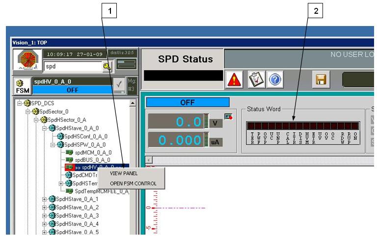
- Actual state (ready, off, tripped…)
- A chart showing the voltage and current trend
- Some leds that detect the actual state (on, rump-up o down...)
- Some boxes providing a summary of the half stave HV setting
Check the box “Status Word” (fig. 10 n. 2) to understand what may have caused the error or the tripped state; for example, in case of a current peak the led “OC” (over current) will be on.
Interpret alert messages: how to handle DSS alarms
- Click the button in the main DCS panel to open it (Fig. 1). This panel displays the alarms set off by thehardware interlocks.
- For instance, should the temperature of a Hs increase all of a sudden and exceed the set limit, the interlock would switch off high voltage in the concerned half sector and the panel would display the related alarm in red (blinking red).
- This panel provides information that may help users to fix problems. The name of detector and the device name appear in the 2nd column. The 3rd column shows the logical name which is useful to understand in what part of the detector the problem occurred. The 4th column provides a short description of the kind of error that has occurred.
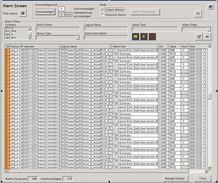
- A – in red – an alarm is active
- W – in yellow – warning message
- E – in orange – error message
- F - Fatal error
- In grey –the error is acknowledged
- A blinking alarm message means that the alarm is still active, therefore the user must acknowledge it. To clear an alarm right-click directly on the cell affected by the alarm in the column “Ack”.
-
The warning messages draw the attention of the users to the abnormal condition or behavior of one or more parts of the detectors. If so, the affected part has to be closely monitored.
If any Fatal error takes place users must contact the on-call expert.
[FOR EXPERTS] How to restart the FSM
- Open the FSM control panel from the button at the bottom of the User Interface (the one with the tools symbol on it).
- Click on the big "Start/Restart all" button in the middle of the panel.
- After the restart the lock is open by default. In case there was an error with the FSMlock, the control can be gained again from here.
[FOR EXPERTS] How to stop/restart WinCC projects
- login on alispdwn001 (spd_a)
- open D:/PVSS_Projects/SideA_DEN (device editor navigator)
- go to the "FSM" tab, click on "stop all"
- repeat points 1. 2. 3. on alispdwn002 (spd_c) and alispdwn003 (spd_dcs)
- do a screenshot of PVSS Console (green boxes)
- on spd_a, spd_c, spd_dcs stop te service called PVSS00mon
- in case you want to reboot, now you can, do spd_dcs first
How to restart the PVSS projects:
- on spd_dcs first, then on spd_a, spd_c restart the service PVSS00mon
- check the PVSS Console for the green boxes, start manually in case they are off (select them and click on the green start button)
- open D:/PVSS_Projects/SideA_DEN
- first on spd_a and spd_c, then on spd_dcs go to the "FSM" tab, click on "start/restart all"
- check that the processes smiSM are 10 on spd_a and spd_c and 12 on spd_dcs
- go to the operator node, kill all the PVSSui processes
- now you can restart the UI
[FOR EXPERTS] How to link the last configuration version inside ACT
- click on the FERO CC button (top right, with the tools icon)
-
specify that a DB version can be considered as good (and linkable):
- click on "Allowable versions" and select the version that you want to link. BE CAREFUL: the versions are not ordered by number
- insert a Description and click on "Set version as allowable"
-
now link this version to the correct run type:
- click on "Current versions"
- select the run type (usually PHYSICS) and click on Modify
- it's not necessary to specify any parameter, select the version from the "Allowable versions" table and click on "Set as current version"
- exit from the panel and check with the refresh button that everything is correct