The SPD has equipment IDs from 0 to 19, each corresponding to the readout of one half sector. Each equipment starts with the Equipment Header (15 32-bit words) of which the last 8 words are known as the Common Data Header, CDH (8 32-bit words). After these headers, sometimes an ex tra header appears (for dedicated calibration runs). This extra header has variable length, depending on the type of calibration scan. Finally, the re is the actual data words, i.e. which pixels are hit in the event. This part has a variable length depending on the number of hits.
- Equipment header and Common Data Header (CDH)
- Calibration header
- Data words (payload)
- Raw data structure and size
Equipment header and Common Data Header (CDH)
The equipment header consists of 15 words. The first word tells the size (in bytes) of the equipment. In the example shown in the eventDump below, the size is 0x2ac = 684 bytes, (or 171 32-bit words). The 11th word (4th word of the common data header) tells which half staves are present in the event. Bit 25 corresponds to half stave 0, 26 to half stave 1, and so on. If the bit is set the half stave is not present. In the eventDump below we see 0x1f000000, which means that only half stave 5 is present. Bit 31 of this word tells if there will be an extra calibration header after the equipment header. In this case there is no extra header, and the data (payload) starts right after the common data header with the first data word 0x6b809fe0.
Example of equipment and common data header from eventDump.
Calibration header
The first word tells the size of this header. The maximum size is right now 16 (32-bit words). In the event dump below, it is 0x00000010, i.e. 16.
Example of event with an extra calibration header.
Below is a table explaining the contents of those 16 words.
| Parameter | Bits | Corresponding word and bits |
| Router Nr | 6 | Word[0] & 0x0000003f |
| Half Stave Scanned (hs) | 6*1 | (Word[0]>>(6+hs)) & (0x00000001) |
| Scan Type | 7 | Word[1] & 0x000000ff |
| Data Format | 1 | (Word[1]) & 0x00000100)>>8 |
| Nr Triggers | 32 | Word[2] |
| Chip Present (hs,chip) | 6*10*1 | ( Word[hs/3+3]>>((hs%3)*10+chip) ) & 0x00000001 |
| DAC Start | 8 | (Word[5]>>24) & 0x000000ff |
| DAC End | 8 | (Word[5]>>16) & 0x000000ff |
| DAC Step | 8 | (Word[5]>>8) & 0x000000ff |
| DAC ID | 8 | (Word[5]) & 0x000000ff |
| Row Start | 8 | (Word[6]>>24) & 0x000000ff |
| Row End | 8 | (Word[6]>>16) & 0x000000ff |
| Row Value | 8 | (Word[6]>> 8) & 0x000000ff |
| DAC Value | 8 | (Word[6]) & 0x000000ff |
| DAC High (hs) | 6*8 | ( Word[hs/2+7]>>(24-16*(hs%2)) ) & 0x000000ff |
| DAC Low (hs) | 6*8 | ( Word[hs/2+7]>>(16-16*(hs%2)) ) & 0x000000ff |
| Test Pulse Amplitude (hs) | 6*32 | Word[hs+10] |
| Misc_Ctrl Delay scan only | 8 | ( Word[7]>>24 ) & 0x000000ff |
| Chip Scanned MinTh scan only | 10 | ( Word[7]>>(16+chip) ) & 0x00000001 |
Data words (payload)
Below is an example of an event displayed with eventDump. Again, only half stave 5 is present.
Example of equipment from eventDump. (Here the extra calibration header is present, but has size 0 according to the 16th word. The data words then start from word 17, byte 64.)
The data words are 16-bit words. To get the words in the correct order you therefore might have to do some swapping, while parsing the data. For example, 0x12345678 ---> 0x5678 , 0x1234
There are four types of data words; header, data, fill, and trailer. The format of their 16 bits is displayed in the table below.
|
|
|||||||||||||||||||||||||||||||||||||||||||
For each chip you expect to have the structure
| Header | 1 word | Start of data from one chip |
| Data | N words | N is the number of pixel hits for the chip |
| Fill | 0 or 1 word | Present only if there is an odd number of data words |
| Trailer | 1 word | End of data from one chip |
In the eventDump example above we then expect to have this structure repeated ten times (once for each chip of half stave 5). Let us look at the first two chips, starting from byte 64:
| 0x6c00 | Header | Half stave = 5 , Event counter = 192 , Chip number = 0 |
| 0x0000 | Trailer | Chip hit counter = 0 |
| 0x6c01 | Header | Half stave = 5 , Event counter = 192 , Chip number = 1 |
| 0xa0d8 | Data | Row = 6 , Column = 24 |
| 0xa522 | Data | Row = 41 , Column = 2 |
| 0xa5e5 | Data | Row = 47 , Column = 5 |
| 0xa7a8 | Data | Row = 61 , Column = 8 |
| 0xabb5 | Data | Row = 93 , Column = 21 |
| 0xb091 | Data | Row = 132 , Column = 17 |
| 0xb142 | Data | Row = 138 , Column = 2 |
| 0xb26d | Data | Row = 147 , Column = 13 |
| 0xb755 | Data | Row = 186 , Column = 21 |
| 0xc000 | Fill | |
| 0x0009 | Trailer | No fastor, No error set, Chip hit counter = 9 |
The event counter should have the same value all over the event. As you probably understand by now, there are lots of consistency checks that can be made on the data. Some of the possible consistency errors are defined here.
Raw data structure and size
A schematic view of the size of the full event is the following :
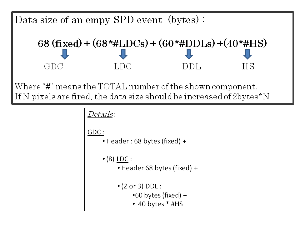
This gives the following sizes (DATE format) in the different events (pp, PbPb):
| Event type | N fired pixels | Corresponding size (bytes) |
| pp collisions (MB) 900 GeV | 50 | 6.712 |
| pp collisions (MB) 7 TeV | 100 | 6.812 |
| PbPb (MB) | 23 K | 52.612 K |
| PbPb (CENTRAL) | 120 K | 246.612 K |