connectors: ⇒Software Wish List ⇒Spd Software Forum ⇒CaenBranchUpdate ⇒Spd Naming Convention ⇒SPDMood
⇒Dac Scans Containers Doc ⇒LtuProblems ⇒Analyzing Consistency Errors
Place to add the software information and news.
Dac Scans Data Structure
By Cesar - 24 April 2006
Here are the structures for the root files to store all the dada for the DAC scans, we will have to multiply the hit arrays by 6, our unit is a router=6 halfstaves
DAC Scans Containers Documentation
Just go to :
Mean Threshold Scan
- nSteps
- integer, the number of dac scans
- sCurves [nSteps][10][32][256]
- integer array constains the scurves (hits) for one Half Stave the size varies with the number of dac scans
- tpAmp[nsteps]
- Table with the Test pulse amplitude, size dependes of number of scans
- dacStart, dacEnd, step
- integers with the dac settings for the scan
- nTriggers
- number of triggers of the scan
Min Treshold
- Hits [nSteps][10][32][256]
- integer array containing the hits for all the dac indexes set
- dacNumber
- Dac number in the pixel chip used for the scan * dacStart, dacEnd, step
- integers the dac settings for the scan
- nTriggers
- number of triggers of the scan
Uni Matrix Scan
- Hits [10][32][256]
- triggers
Mood Headers
By Ivan - 27 June 2006
So now in the raw data we will have this new information, The folowing example is for a Mean Threshold Scan.
- Eq. Header
- Scan Header
- Header lenght
- Router Number (bit 0..5 : RouterNumber, bit 6..11: HS scanned)
- Type (bits 0..7 operation mode, bit 8 : 0 = Normal data, 1 = Histogram format)
- Triggers
- Chip Present 1 (HS 2, 1, 0)
- Chip Present 2 (HS 5, 4, 3)
- DACStart, DACEnd, Step, DAC Identifier (8 bit registers)
- Row start, Row end, DAC Index/ row index (8,8,16 bits)
- DACHigh0, DACLow0, DACHigh1, DACLow1,DACHigh2 (HS 0,1)
- DACHigh0, DACLow0, DACHigh1, DACLow1,DACHigh2 (HS 2,3)
- DACHigh0, DACLow0, DACHigh1, DACLow1,DACHigh2 (HS 4,5)
- TPAmplitude0 (*100)
- TPAmplitude1
- TPAmplitude2
- TPAmplitude3
- TPAmplitude4
- TPAmplitude5
- Raw Data
Operation Mode:
- 0 Minimum Th
- 1 MeanTH
- 2 Generic DAC Scan
- 3 Uniformity Scan
- 4 Noise Scan
DAC Identifier:
- 0 .. 44 pixel chip DACs
- 100 .. 108 API DACs
Command Agent
By Cesar - 31 Mar 2006
Data Point Structure
- Currid (int)
- Received
- Data (dyn_uint)
- ID (dyn_uint)
- Errors (dyn_string)
- Pending
- ID (dyn_uint)
- Commands ( not used yet but soon)
Send Command structure
| 0 | Size |
| 1 | ID |
| 2 | Channel |
| 3 | Offset |
| 4-24 | Command |
| 25-end | DATA |
Answer from the FED Structure
| 0 | Size |
| 1 | ID |
| 2 | Status |
| 3 | Channel |
| 4 | Offset |
| 5-25 | Command |
| 26- end | Data |
In the begining there is a dpconnect to automaticaly take data out from the dim datapoint and to update the pending and received data points Each time there is an error ( status <nop>= 0) just appends one string like this : " id: command : error_code " in the error list data point. There are functions to send the command and to get the data parsing all the fields so things should be easy to use. At the moment there is no automatic time-out for demands, but I suppose that that's the next step. This thing now needs to be integrated in the fed Server to have the full structure integrated.
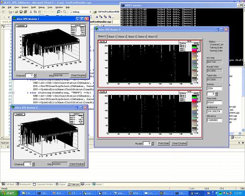
First Uniformity Matrix Scan
First Uniformity Matrix Scan Sreenshot:
Uniformity matrix scan Header
By Ivan -06 Feb 2006 void StartScan(UInt8 ChN, UInt32 triggern, UInt32 * CHSelect, UInt8 rowSt, UInt8 rowEnd, bool MSKNoAct, bool Tp);
Instructions:SCN_UNIFORMITY_ START, STOP, RESTART
I need that PVSS sends to FED togather with the start command (UInt32 stream)
- 0 total stram lenght
- 1 Channel Number (> 119 broadcast)
- 2 trigger number (max 27 bit)
- 3 row start Scan
- 4 rowEns Scan
- 5 Mask no actice row
- 6..125 120 ChSelect (bit 0 = chip 0 active and so on)
pixelPresent and pixelStatus Data Point Structure
- spd_fe_dcs:HSCh.pixelPresent (32bit DataPoint): (Ch=000,001,...119)
- 0 Pixel0
- 1 Pixel1
- ...
- 9 Pixel9
- bit = 0 pixel not present
- bit = 1 pixel present
- spd_fe_dcs:HSCh.pixelStatus (32bit DataPoint): (Ch=000,001,...119)
- 0,1 Pixel0
- 2,3 Pixel1
- ...
- 18,19 Pixel9
- bits 00 "Not Present" color Dark Garay
- bits 01 "OFF" color _3DFace
- bits 10 "ON" color Green
- bits 11 "TEST" color Blue
Mean Threshold scan
By Cesar - 10 Feb 2006
Data General Data Header
- 0 Size
- 1 Channel
- 2 Type
- 4 Pixel Select {HS 0 - 2}
- 5 Pixel Select {HS 3 - 6}
By Cesar - 10 Feb 2006
Important In Order to make all scan work, so the FED server can know tupdate the type of data, the system has to be set in buffered mode
By Cesar -10 Feb 2006 Panel already implemented by Simone. Change on the data format in the PVSS-> Analysis Tool
- Commands PVSS-> AnalysisTool:
- ROOTC_START_MEANTH:
- DACStart,
- DACEnd,
- Step,
- Trigger Number
- Pixel selected {0 - 2}
- Pixel selected {3 - 5}
- With the Dim command ROOTC_STOP_MEANTH:
- ROOTC_START_MEANTH:
By Ivan -09 Feb 2006
- Commands PVSS-> AnalysisTool:
- ROOTC_START_MEANTH:
- DACStart,
- DACEnd,
- Step,
- (UInt32)HS[i + ChNumb].GetChipSelected() << (i%3 * 10); i = 0..2 ,
- (UInt32)HS[i + ChNumb].GetChipSelected() << (i%3 * 10); i = 3..5,
- ROOTC_STOP_MEANTH:
- ROOTC_START_MEANTH:
- FED-> Analysis tool : with the data
- General Data header
- Header[0] = DACTPlow + DACTPHigh << 8 + DACIndex <<16;
- Header[1] = (UInt32)(TPAmplitude * 100);
- Raw data
By Simone -10 Feb 2006
- Commands PVSS-> FED:
- SCN_MEANTH_START with this data:
- 0 total stream lenght
- 1 Channel Number (> 119 broadcast)
- 2 trigger number (max 27 bit)
- 3 row start Scan
- 4 row end Scan
- 5 DAC Start Value
- 6 DAC Stop Value
- 7 DAC Step Value
- 8 Mask no actice row
- 9 DCS Active
- SCN_MEANTH_START with this data:
-
- SCN_MEANTH_STOP
-
- SCN_MEANTH_RESTART